Complications
|
Fracture Fixation Complications |
|
|
|
|

|
Complications of Fracture Fixation
by Jason R Wild, MD
Implantable orthopedic devices have been used since the early twentieth century for treatment of skeletal maladies. Modern treatment of orthopedic diseases including fractures, degenerative diseases, and other deformities involves the use of metallic and nonmetallic implants. Over the last century, significant advances have been made not only to the implants themselves, but the techniques and methods in which they are used. Ever since the first orthopedic devices were implanted, complications have been noted (Ruedi, 2007).
Fixation
Most orthopedic implants require fixation into bone or soft tissue for stability and function. This fixation is achieved in several ways. The most basic fixation relies upon friction fitting. Smooth wires (Kirschner wires or K-wires) are spun into the bone and, once in place, friction between the wire and the bone holds them in place (Ruedi, 2007; Althausen, 2002; Jauregui, 2015).
Screws are commonly used orthopedic implants and can function independently or as part of a construct. Screws can function in many different ways, either by design, or by the method in which they are applied. They can serve as a simple anchor for attaching objects such as suture, tendons, or plates to bone. They can be used independently, as a means to compress or maintain position of a fracture (Benjamin, 1994). At the functional level, screws also rely upon friction between the threads and the bone to achieve stability. When used with a plate, the screws themselves compress the plate to the bone surface. Once tightened, the plate is kept in place and motion is prevented by friction between the undersurface of the plate and the bone (AAOS, 2008).
The use of a wedge is another way implants exploit friction for their attachment to bone. The most common example of this is a tapered hip prosthesis where the device is wedged into the proximal femur to achieve stability. As the implant is loaded, it further compresses the implant/bone interface. Some of these implants are designed to then allow bone to in-grow and attach directly to the prosthesis – using a porous surface, and sometimes a hydroxyapatite coating that allows for a molecular level attachment to the bone.
Cement is another option for fixation. Cement is usually pressurized or pushed into the trabecular bone, where it interdigitates to achieve “purchase” into the bone at the cement-bone interface. The implant is then placed into the cement “mantle” before the cement hardens creating a perfectly conformed fit between the cement and the implant. This cement-implant interface relies upon a friction fit for stability.
Other devices such as buttons and anchors are also used to attach sutures or soft tissue to bone and are designed to resist tensile forces.
Finally, some devices do not achieve rigid fixation to the bone. Intramedullary nails, for example, are placed within the medullary cavity. They are often held in position by interlocking screws. While the screws have stability in the bone, the interface between the screws and the nail has a considerable degree of tolerance allowing for macroscopic motion of the nail and thus macroscopic motion at the the fracture site.
Back to Top
Back to Top
Device Failure
Orthopedic devices, like any mechanical object, can fail in many ways (Gelman, 1984; Benjamin, 1994; Berquist, 1995; Freiberg, 2001). The implant itself may fail by breakage, or the bone-implant interface may fail with loosening or fracture (figure: migration of fracture fixation pin; figure: plate loosening and screw displacement; figure: displaced suture anchors; figure: failed LCD plate).
Prosthetic joints are subject to loosening, wear, and dislocation (figure: dislocated hip prostheses). Failure can also occur iatrogenically through improper or inappropriate placement (figure: dynamic compression screw projecting into right hip; figure: fixation screw going into hip; figure: helical screw in hip; figure: retained drill guide; figure: iatrogenic caused failure of left hip fracture).
Lastly, the bone can fail around orthopedic implants, often termed periprosthetic or peri-implant failure (figure: right femur periarticular plate breakage; figure: right shoulder implant periarticular fracture; figure: right femur supracondylar periprosthetic fracture).
The causes of failure are multi-factorial and may involve such patient factors as non-compliance, infection, and poor bone quality; or, they may simply be related to everyday mechanical factors such as normal wear and tear or excessive use with increased wear and tear (figure: fracture fixation failure patient ambulating against advice).
In general, orthopedic implants are more rigid than the bone to which they are fixed. The “quality” or density of the bone is tied directly to the fixation strength of most orthopedic implants. Any loss of bone quality can negatively affect their purchase. Location of the implant can also play a factor because bones are anisotropic and not uniformly dense throughout their length. As diaphyseal bone is far thicker and denser than metaphyseal bone, an implant which achieves fixation in diaphyseal bone may have stronger fixation than an identical implant placed in the thinner metaphysis or epiphysis.
Radiographic detection of implant failure may be obvious or very subtle. When devices themselves break, a radiographic view parallel to the failure plane may be necessary to detect the failure. When failure occurs between the bone and the device, the findings may be more difficult to detect. Healthy bone is in a dynamic state of turnover, and over time it responds to stress by laying down more bone in these areas of high stress according to Wolff’s law.
Orthopedic implants can change the forces the bone experiences, and therefore bone may change in response to the presence of an implant. An example is when an implant reduces the stress on a bone leading to a relative osteopenia, termed “stress shielding;” (figure: stress shielding). Stress loading is an increase in bone density from altered stress distribution to native bone from an implant (figure: stress loading). This unique ability of bone to adapt to loads under which it is placed can give radiographic clues as to the status of the bone/implant interface and possibly to the state of fracture healing or arthroplasty fixation. Detecting these changes as well as signs of loosening or failure of orthopedic implants may be difficult, so chronological comparison of radiographs is imperative.
Back to Top
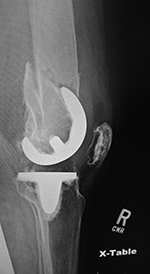
| Right femur supracondylar periprosthetic fracture |
 |
 |
 |
 |
| 74 year-old women who was in an automobile accident and suffered a right femur supracondylar periprosthetic fracture about her cruciate retaining TKA. The fracture was treated with a lateral periarticular plate and screws. |
 |
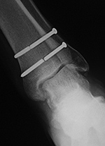
| Left ankle syndesmotic screw fracturing |
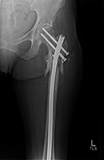
Left hip cannulated screw fracture |
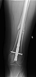
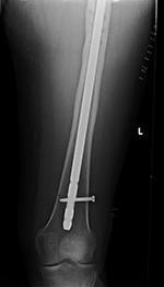
Right femur retrograde intramedullary rod (nail) extrusion with fracture of distal locking screw |
 |
 |
 |
 |
| 22 year-old man with syndesmotic screw placement for medial avulsive ankle injury. The screws fractured and loosened being later removed. |
41 year-old man with chronic left femoral neck fracture and fracture of superior cannulated fixation screw. The partially visualized intramedullary nail is for an old femoral shaft fracture. |
46 year-old man with healing distal femoral fracture
|
|
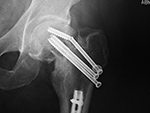
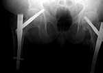
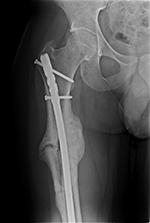
| Fixation screw projecting into right hip joint |
Right femoral neck helical screw displacement with penetration of the right acetabulum |
 |
 |
 |
 |
| 60 year-old woman treated for right hip intertrochanteric fracture with lateral stabilizing trochanter plate, dynamic compression screw, and separate cannulated fixation screw which extends into the right hip joint. |
There are bilateral short femoral nails with helical femoral neck screws. The screw on the right has penetrated the right acetabulum. |
|
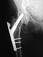
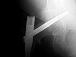
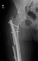
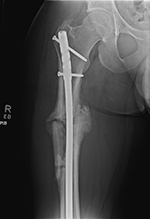
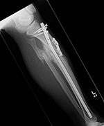
| Settling of right hip dynamic compression screw |
Interlocking fixation screw loosening, breakage, and troughing |
 |
 |
 |
 |
| 65 year-old man with basicervical hip fracture treated with dynamic compression screw and sideplate. The fracture had delayed healing, and ten months after screw placement settling of the fracture significantly displaced the compression screw. |
Intertrochanteric femur fracture from a bullet wound treated with a long intramedullary nail, two proximal cannulated partially threaded femoral neck screws, and two distal interlocking screws. The interlocking screws have fractured, partially pulled out of the femur, and troughed through the femur producing horizontal linear areas of lucency. |
|
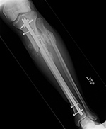
| Hypertrophic nonunion |
Loose femoral interlocking screw with "backing out" from the bone |
|
 |
 |
 |
|
| A distal femoral shaft fracture treated with a long intramedullary rod shows delayed healing with hypertrophic nonunion. |
The interlocking screw in the distal portion of the femur is loose and has partially backed out of the bone. Skin staples are also evident. |
|
Back to Top
Complications of Fracture Fixation
Fracture Treatment
Several types of orthopedic implants are used in the treatment of fractures -
Wires (K-wires, Steinmann pins, Rush rods, Ender nails, flexible nails, cables; intramedullary (IM) rods/nails); Screws (cancellous, cortical, lag, cannulated, headless, interlocking); and Plates (tubular, reconstruction, compression, locking, blade) - to name the more common examples. These are discussed and illustrated in more detail in the Fracture Fixation portion of this website.
Stability (stiffness) represents the displacement between fixed fracture fragments when a physiologic load is applied. A stable fracture does not displace under a physiological load. Stability is a principal determinant of whether a fracture is treated conservatively or operatively (Bartolotta, 2019).
The principle goal of fracture treatment is restoring length, alignment, and rotation of the fracture, and maintaining it until the fracture heals (Ruedi, 2007). This can be performed with splinting or casting or through surgical fixation. Healing occurs either primarily or secondarily through a cartilage intermediate. Fractures involving the joint surface usually require anatomic reduction and stable fixation to prevent arthritis and to allow for early motion of the joint to preserve mobility and cartilage health (Muller, 1965).
Direct or primary bone (fracture) healing occurs when absolute stability is maintained after an anatomic reduction is achieved, and the fracture ends are compressed together. Direct bone healing requires there be no gap or motion at the fracture site. In this mode of bone healing, the standard bone turnover process continues as if no fracture is present. The fracture heals directly with new bone formation. The hallmark of this type of healing is the fracture line disappears without the formation of callus.
Indirect or secondary bone (fracture) healing occurs through a cartilage intermediate. Motion at the fracture site creates a micro-environment which causes healing to proceed through several phases: a) inflammation, b) soft callus formation which is predominated by cartilage that helps reduce the motion/strain at the fracture allowing for bone deposition with c) transition to hard callus formation, and finally d) bony remodeling.
Nonunion
Nonunion of a fracture is considered when 6 months have passed and the fracture has not healed, or if 3 consecutive radiographs show no progression towards healing. Nonunions can be divided radiographically into three main types: oligotrophic, atrophic, and hypertrophic. Each of these occur in response to a unique environment. Detection of nonunion can be challenging. The use of dynamic radiographs, oblique views, and advanced imaging can aid in diagnosis.
Oligotrohpic nonunion often occurs when the bone has been devitalized, either by soft tissue injury which occurred during the fracture, or iatrogenic insult caused during the surgery. Because the blood supply has been damaged, the fracture is frozen in time without resorption or progress towards healing. Often patients are non-weight bearing which causes the surrounding viable bone to undergo relative atrophy or resorption according to Wolff’s law. This leads to a relative hyperdensity of the avascular bone which retains the same density it had at the time of injury/vascular insult. Without vascularity, these non-unions have poor healing potential. Debridement of the dead bone and bone grafting are often required to achieve union.
Atrophic nonunion usually occurs when the fracture site has vascularity and does not generate sufficient callus to bridge the fracture site. This often occurs in response to a fracture fixed with too large of a fracture gap. The bone has some viability but no stimulus to heal, and therefore resorbs at the fracture site without evidence of bony union. Revision of fixation and bone grafting are often required for bony union. Occasionally, if the implants weaken or break, motion may occur which can stimulate the healing process.
Hypertrophic nonunion occurs when vascularity of the fracture is preserved, but there is too much motion at the fracture site, and the callus cannot actually bridge the gap. Hypertrophic nonunion can sometimes progress towards final union if the fracture eventually achieves stability through the abundant callus (figure: hypertrophic nonunion; figure: hypertrophic nonunion with later bony union). Surgical compression of these viable hypertrophic nonunions provides increased stability and leads to a high rate of bony union.
Fracture vascularity and stability thus have a direct impact on the type of healing that is observed. Infection at the site of a fracture can also lead to nonunion (figure: right femur periarticular plate breakage). Radiographic clues of infection can be sequestrum formation, or associated abscess found on advanced imaging (CT, MRI, ultrasound, or nuclear medicine studies), but usually infection is a clinical diagnosis.
Back to Top
Fracture Fixation Failure
Implants used in fracture fixation are designed to maintain the position of the fracture while the body’s natural healing takes place. While most implants are designed to left in place after healing, they have a finite working lifespan. Once implants have been placed, a race begins between the fracture healing and the implant failing. If the fracture heals in a reasonable time (3- 6 months), the implant is unlikely to fail, and the bone assumes the vast majority of load bearing. In the presence of a nonunion or delayed union, the implant will continue to experience loading, which if above its fatigue threshold, can lead to its failure or loosening (figure: failed LCD plate; figure: right femur periarticular plate breakage). Similarly, implants placed across joints or spaces where there is natural motion after healing are also subject to delayed failure, as seen in illiosacral and ankle syndesmotic screws (figure: metatarsophalangeal joint arthrodesis screw fracture; figure: ankle syndesmotic screw fracture).
If the load placed on an implant exceeds its ability to resist that load, the construct is subject to failure (figure: femur intramedullary nail fracture; figure: hip cannulated screw fracture; figure: femur IM rod slippage and locking screw fracture; figure: settling of dynamic compression screw into hip). This scenario can be observed in cases of patient noncompliance with weight bearing restrictions, or when the construct is too weak, such as in poor implant design or application, or in the setting of poor bone quality (figure: fracture fixation failure patient ambulating against advice).
Screws can be used by themselves to join 2 parts of the bone, or they can be used to attach something to the bone such as a plate, suture, or soft tissue. Screws may fail by loosening or breaking. Screw loosening can be detected by a radiographic “halo” around the screw, where the screw/bone interface has been compromised. Motion of the screw compresses the surrounding bone which generates this appearance and compromises fixation. The screw may then begin backing out or migrating as it becomes loose (figure: loose interlocking screw). Interlocking screws used in intramedullary nails can also trough through the weak metaphyseal bone. This troughing may be detected by comparison of the screw potion to earlier radiographs as well as by identifying the path which the screw has cut through the bone (figure: broken interlocking screws with troughing).
Implants may also bend or break in an area of high stress concentration, or they may induce abnormal weight bearing leading to an implant related stress fracture (figure: Zickel nail; figure: distal tibial stress fracture). This is seen commonly when screws are placed across joints and continued motion causes breakage of the screw, usually near the joint, where the motion is occurring (figure: metatarsophalangeal joint arthrodesis screw fracture). Screws may also break as part of a larger construct failure. Screws are usually weaker than plates and often fail by fracturing near the bone/plate interface (figure: plate loosening and screw displacement; figure: failed LCD plate).
These and other screw fractures may be difficult to detect if the broken ends do not displace. Radiographs directly parallel to the (screw) fracture plane may be necessary to reveal the failure. Plates and nails can similarly be subject to failure by bending or breaking. This often occurs around areas of high strain concentration, such as at a nonunion or persistent fracture site that has poor bony stability. The detection of failure of fracture fixation apparatus when it is subtle can be quite difficult. It is therefore necessary to stringently compare prior imaging studies, usually radiographs, to the most recent study to detect untoward changes in the implant or bone over time.
Back to Top
| Initial Hypertrophic nonunion going on to subsequent full bony union |
|
 |
 |
 |
|
| The initial image (left) shows a complex proximal femoral shaft fracture treated with a long intramedullary nail. A subsequent image (middle) several months later shows hypertrophic nonunion. The third image (right) several more months later shows final solid bony healing medially. |
|
|
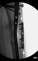
| Failure of fracture fixation due to ambulating against advice |
 |
 |
 |
 |
| Male patient with proximal tibia and fibula fractures treated by intramedullary nail and supplemental one-third tubular plate. Initial intra-operative fluoroscopic AP and lateral images (left two images) show the plate (arrow on lateral image). The patient ambulated against advice and was lost to follow-up. Two months later he again presented (right two images) to the clinic. There is now tibia fracture migration, and the proximal medial to lateral interlocking screw has backed out (AP view). The lateral view demonstrates fracture displacement with flexion deformity. The nail has troughed outside the proximal anterior tibia and is sitting within the soft tissues. The supplementary plate is broken, there is a broken interlocking screw, and abundant fracture callus is present. |
|
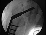
Iatrogenic fracture fixation failure |
Left ankle stress fracture |
 |
 |
 |
 |
| Intraoperative fixation of an intertrochanteric fracture demonstrates a cephalomedullary device with the tip of the cephalic screw positioned too short and very inferior in the neck (very large tip-apex distance). |
Subsequent fracture fixation failure observed as the head and neck segment of the femur flexed 90 degrees with cut-out of the screw approaching the hip joint. |
Several weeks prior the patient had been treated for a distal fibular fracture with a fibular side plate and interfragmentary screw. Altered weight-bearing caused by the ankle injury and the plate and screws led to a stress fracture (arrow) in this elderly patient with poor bone stock. |
|
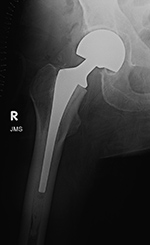
| Stress shielding |
Stress loading |
|
 |
 |
 |
|
| 69 year-old woman with right femoral neck fracture treated with bipolar hip prosthesis (left image). Five months later (right image) there is reduction of femoral cortical thickness (lower two arrows) and osteopenia in the greater trochanter (top arrow) from stress shielding. |
52 year-old man with right total hip arthroplasty 7 years previously. An AP radiograph of the pelvis shows the arthroplasty with considerable thickening to lateral and medial femoral cortices from stress loading. A right iliac reconstruction plate is partially visualized. |
|
Back to Top
|


